“Encircled Flux”= More Accurate Multimode Fiber Measurement Technology
Measurement In-Accuracy
Multimode fiber cabling as part of what is commonly referred to as "universal structured building cabling" and is typically evaluated either by a loss measurement (LSPM = Light Source + Power Meter = Tier 1) or an OTDR measurement (OTDR = Optical Time Domain Reflectometer = Tier 2).
Large variability in test results can occur especially in loss measurements depending on the measurement equipment used. To get comparable measurement results, standardization bodies have agreed on new definitions of loss measurements on Multi mode fiber cabling. Accuracy enhancement is achieved by the specification of reference methods and the tolerances for the measurement tools
used, and by the specification of the test signal used.

Cleanliness
Cleanliness and lack of defects are of utmost importance for fiber optic cabling and, of course, also for the fiber optic measurement equipment. In order to verify the cleanliness and the condition of the fiber connectors of the reference cords (measurement cords) and of the fiber cabling under test, it is critical to inspect the end faces of the fiber connectors included in the test with a fiber inspection microscope each time before a measurement is carried out. If the connector end faces are contaminated, they can be cleaned and reinspected.
At that point, if everything is clean and free from defects, only then should the fiber connectors be mated! Any other way of proceeding can result in incorrect results. More over, careless handling of the fiber connector end faces can cause damage that leads to a complete failure of the fiber cabling. (see figure 1)
Optical Attenuation (Loss)
To be able to understand the impact of “Encircled Flux” on measurement equipment, you need to know the fundamentals of fiber optic loss measurement. How can attenuation in fiber cabling be measured? It sounds quite simple. One uses a light source (LS) and a power meter = PM and measures the optical power that is getting lost on the fiber run. Hence attenuation (loss) is:
L [dB] = 10 * log (Pin / Pout)
Or, if the power meter used is able to display the measured light power levels directly in dBm, then loss can be computed by simply subtracting the input power received (PPM [dBm]) from the output power (PlS [dBm])
L [dB] = PLS [dBm] – PPM [dBm]
This seems to be quite easy, but the devil is in the details, because it is necessary to set reference before a measurement is performed to exclude the measurement equipment itself from the overall measurement. The quality of the measurement cords and connectors directly affects the accuracy of the result. In order to get the correct relative measurement value, it is required to determine the output power of the light source (PLS) and to store this value as a reference value in the power meter.

Referencing
For setting reference, the standards organizations have defined the use of one to three reference measurement cords. There are various conditions – i.e. how and how much light (more precisely light modes) is coupled into the fiber. In recent years the coupling light into a fiber has become an issue again and the definition of "Encircled Flux" was included in the standards.
But how was it done before? Initially, the use of LED light sources was standardized. These produce are referred to as overfilled launches.. referred to as an "overfilled" launch (see figure 2a).
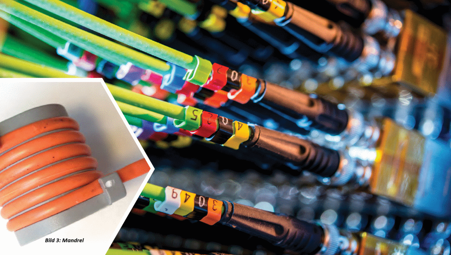
This "overfilling" was not particularly clever, because an overfilling with the light emitted by the LED light source will not only launch light modes into the fiber core but into the cladding as well, that propagate in the fiber as stable modes of lower order (near the center of the fiber core) and as unstable modes of higher order (further away from the center of the fiber core, and even in the cladding). When using short reference measurement cords, this resulted in measuring too much light with a power meter when setting reference. In turn, this led to inaccurate measurements, because the measured reference power was too high due to the cladding modes. In addition to this, in longer cable runs, the unstable modes of higher order in the fiber cladding and partly also in the fiber core tend to disappear after some distance and then will no longer be part of the measurement. To ensure more stable conditions, the so-called cladding modes and the unstable higher order modes are already filtered out by means of a mode filter (mandrel) before setting reference (see figure 3). Somewhat more stable measurement conditions were created with this method, however, the loss readings were typically still too high and therefore too conservative.

As VCSEL (Vertical Cavity Surface Emitting Laser)
Based light sources (see figure 2b) were employed in the measurement equipment (these were often used in the active equipment deployed in transmission lines e.g. 1GbE SFPs with 850nm VCSEL) but produced measurement results that were too optimistic, because of an insufficient illumination of the fiber core and too small a number of higher order modes launched. Moreover, certain faults, such as an offset of the fiber cores in a mated fiber connection, were unable to be detected. These two launch conditions - "overfill" and "underfill" - were likely to produce measurement variability that significantly exceeded 10%, which was not especially critical in the the past times of ample system headroom in fiber links. But with today’s increased data rates such as 40GBASE-SR4 / 100GBASE-SR10 over OM3 or OM4 fibers with lengths of 100 / 150m and a acceptable Channel loss of merely 1.9 /1.5dB, such a large system headroom no longer exists, and variability exceeding 10% is unacceptable. Standardization bodies responded with launch methods that eliminate such a high degree of variability with an exact definition of the light power distribution in the fiber core. This definition is named „Encircled Flux“ and is between an "overfilled" and an "underfilled" launch.
"Encircled Flux" Definition:
As specified by the standard, Encircled Flux is the portion of the cumulative (summed) power of the near field relative to the overall output power as a function of the radial distance from the optical center of the fiber core. By way of an exact measurement of the light power through a near field measurement, it can be exactly determined how many modes of lower and higher order are launched into the fiber for the measurement and hence into the fiber core of the link under test. Please refer to the IEC 61280-4-1 standard for the light power ratios specified for the various core diameters and wave lengths. The values and tolerances are fixed in the EF template, as upper and lower bounds in near field measurements carried out with laboratory measurement equipment. Now, that we have thoroughly explained the light sources, there is another challenge to be faced. Standard specifications demand that the Encircled Flux launch condition is not present at the output of the light source, but at the end of a reference measurement cord to ensure that Encircled Flux compliant mode power distribution is fully achieved in the fiber optic cabling under test.
"EF" until the Point of Insertion
In the case that the light source itself provides the "Encircled Flux" launch condition, EF until the point of insertion can be achieved with special "modally transparent" reference measurement cords. In this way it can be ensured that the light coupled into the cabling link under test, exactly meets Encircled Flux conditions at the output of the launch cord / reference connector. The benefit of this method over other Encircled Flux methods (e.g. a mode conditioner placed
between the light source and the reference connector) is that replacing the worn reference connector of a reference measurement cord will be relatively inexpensive, as you can simply buy a new modally transparent reference cord. When comparing different measurement instruments, the variability of measurement results is well below 10%, due to the clear definition of the modal distribution at the reference connector by Encircled Flux.

Conclusion
With loss budgets getting increasingly tighter, it is imperative to employ measurement equipment complying with "Encircled Flux" launch conditions to get reliable and accurate results in the certification measurement of Multimode fiber cabling. This is the only way to ensure that modern fiber optic high-speed applications can be operated without problems.
Author: Thomas Hüsch, Technical Support & Training

