Near-end crosstalk attenuation between the wire pairs (NEXT)
Classic call on a morning in the support department of a manufacturer of measuring devices for certifying network links: "The tester here is probably broken, keeps showing NEXT errors! What do I have to do?". Simple question, but difficult answer because very complex, so first clarify the facts! The installer has built a passive copper data network and is now trying to carry out acceptance measurements with a cabling certifier borrowed from the specialist wholesaler, obviously with little success. In order to be able to help him out of his predicament professionally, one should understand what the claimed measurement parameter NEXT stands for and what causes it to fail.
NEXT is the abbreviation for "Near End CrossTalk", i.e. signal crosstalk at the near end of a data line. Crosstalk from one pair of wires to another pair of wires is an undesirable effect because induction causes noise signals on the other pairs of wires, which can interfere with signal transmission. If the undesired noise signals are higher than permissible, the receiver can no longer clearly recognise the signal intended for it and the data stream is changed or interrupted.
This high-frequency crosstalk of the cabling link is measured over a frequency range that is determined by the selection of the measurement standard and must be adapted to the performance of the link. The achievable near-end crosstalk attenuation values are in fact directly dependent on the quality of the components and cables used, but also on the processing when laying the cables on the connection components. The measurement of near-end crosstalk attenuation is the determination of how many signal components Tx are transmitted from one pair of wires to an adjacent pair of wires Rx at the near end (Fig. 1).

In the case of a four-pair cable, measurements must be taken from each pair of wires to each of the other pairs of wires. In the case of a four-pair cable, this means 4 X (4 - 1) measurements, i.e. a total of twelve measurements. However, since the measurement from pair 1-2 to pair 3-6 yields the same results as a measurement from pair 3-6 to pair 1-2, it was agreed that only six measurements should be carried out. However, since the effect of crosstalk is only felt about 30 to 40 m away in the wire pairs, these measurements must be taken from both sides of the cable section, which again gives a total of twelve NEXT result sets. The measured values over the frequency points are displayed as a progression curve and the smallest distance to the limit value curve is used as the worst value to evaluate the cabling section according to the standard. Back to our installer at the other end of the telephone line. After the short excursion into the theory of crosstalk, back to the acute problem. As you can already see from the introduction above, there are obviously several influencing factors that decide on "top or bottom". These must now be worked through in order to find the cause of the problem.
Quality of the installed components
First of all, it must be clarified whether the installed system is at all suitable for the applied measurement. A data link consists of at least three individual components, the laid cable and the connection components at both ends. These are typically a data socket on the user side and a distribution panel in the control room. Each individual component determines the overall performance and must be of sufficient quality. The table in (Fig. 2) shows the correlation between the power category of the installed individual components and the achievable distance class.
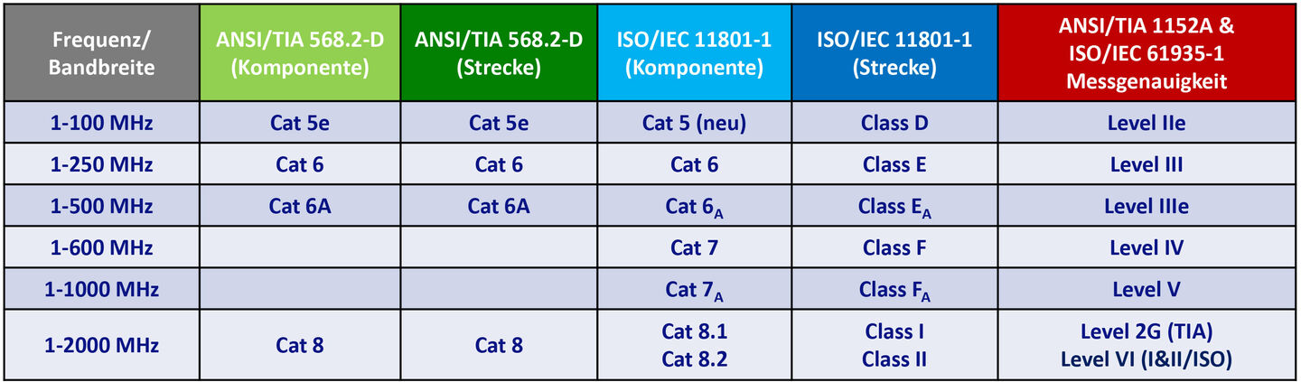
Note also the difference between the American track definition, which bases its designation on the components, and the international/European one, which clearly distinguishes between "category" for individual components and "class" for the assembled track. A track can only be as good as the weakest component in the assembly. A category 5 data socket does not get better even if a category 7 cable is used and the performance remains at class D level. An important special case is the famous "A" (stands for English "augmented") in the 500 MHz components. With the same bandwidth, these components have different NEXT characteristics, depending on which cabling standard they are oriented to. If you use the manufacturers commonly used in our country, the components are categorised with "6A" (with a subscript "A"!) and are fully suitable for use in a class EA link. Components with a designation of only "6A" ("A" at the height of the number) may well fail a class EA link measurement, as they have less crosstalk reserve because they are only designed for the weaker American Cat6A link definition.
Of course, the measurement standard on the unit must be set to match the nominal quality of the draw frame. To stay with the above example, the correct setting for a link that consists of at least category 6A components, as is common today, is the performance class "EA". For the topology of the measurement, there are two variants, the so-called "permanent link", where the measurement starts at the transfer point in the distribution panel and ends at the box, and the so-called "channel link", where the measurement also includes the connection cables, or measurement cables. However, this type of measurement is not intended for acceptance measurements, as it also includes parts of the route in the measurement that do not belong to the installation route and also leaves room for conscious and unconscious false statements. Once we have clarified on the phone that the link quality and the measuring device settings should theoretically result in a "pass", we get down to the nitty-gritty. Since the measurement results of a track depend on many individual components, it is now necessary to localise the source of the error. Let's break down the measured distance to identify the factors influencing NEXT errors. The measurement chain and thus the potential sources of error include: the local and remote units, the measurement adapters, the measurement cables, the measurement connectors on the measurement unit side. On the system side: the connection components and the cable. Now it is first necessary to clarify, if possible without much effort, who is now the cause of the failure, the measuring device side or the system, in order to then continue research on the right front.
"Measuring device or annex, that is the question here!"
A simple way to determine the main source of error is to look at which side of the track the error is on after a NEXT error measurement. Since nowadays the components are usually responsible for NEXT errors, either directly or indirectly, the errors are to be found either at the front or at the rear. By now, most measuring instruments can determine this quite accurately. Then reverse the measurement, i.e. change the connection side (including the measuring cables!) and repeat the measurement. If the error that was previously on the LOCAL side, for example, now migrates to the REMOTE unit, you know that the system is probably the source of the problem and you can look at the sources of the error there. If, however, the error has also migrated, i.e. has remained on the same unit, one must turn to the measuring equipment.
"General recommendation to measurement squads on the road with cabling certification: Always be able to quickly isolate the main sources of your NEXT problems. Build a reference section of high quality components in the workshop and measure it with your measuring instrument when it is freshly calibrated and equipped with new(value) measuring cables or tips."
Alfred Huber, Head of Technology, Softing IT Networks GmbH.
Once the measurement equipment has been identified as the probable cause, the next step is to rotate the set-up again, but this time leave the measurement cables plugged into the ports and only replace the devices themselves in order to determine whether they are the cause of the problem. In most cases, you will already be successful here, as the NEXT measurement also suffers from wear and tear of the measuring plugs due to repeated plugging. Replacing them with new ones is often the key to success. If not, the adapters remain on the port on the next test level in addition to the measuring cables. You can continue this interplay all the way down to the device units in order to pin down the fault.
A special case is possible if the installer, against all custom, uses the "channel link" measurement and tries to carry out a measurement with unfortunately inferior patch cables (patch cables that do not correspond to the category) and thus always fails at this weakest link of the measurement chain. However, this should not be the case for acceptance measurements, where "permanent link" measurement is the order of the day.
System as a source of error
If the first quick tests have shown the system to be the culprit, it is important to successively work through the potential sources of error. First of all, of course, check whether the components of the correct category have really been installed. If so, then you must assume either a batch error of the components (very, very rare!) or possible defects in the workmanship when connecting. Especially if components in the classic LSA technology were still installed, there are some errors that you can make yourself. Probably the general error is opening the twisting of the wire pairs of the cable too far during installation. Maintaining the twisting of the wire pairs is extremely important in achieving the crosstalk properties of a line. The twisting of the wire pairs and the pairs to each other is where the NEXT properties of the cable are located. Any change in these ratios leads to a deterioration of the NEXT performance and even to transmission failure. Therefore, it is extremely important not to twist anything up here or even invent your own twisting system. The rule of thumb for this is still 13mm per side and no more. It should go without saying that the pair systems must not be broken up and recombined. The "split pairs" error sends its regards! Here, new pair combinations are formed on both sides of the track, which result in a 1:1 connection in ohmic terms, but no longer carry their signals in the cable pairs. A classic example of this is the swapping of two white wires on both sides. Another source of error can be removing the wire pair shield foils too far during installation. In our shielded systems, especially in higher transmission classes from class EA and higher, the individual shields are also an important component for achieving the required performance class. To get back on track here, it is often sufficient to reconnect or reconnect the respective component(s), but this time in compliance with the specifications from the manufacturer's instructions.
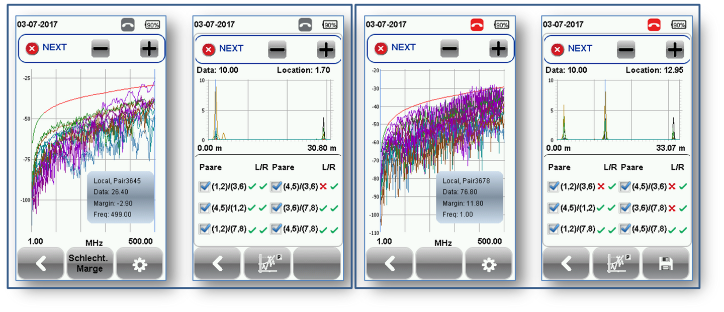
- Component of too low category installed on LOCAL side
- Cable "patched" with luster terminal after approx. 13m from LOCAL device
If the measurement shows the installation cable to be the (rare) cause of the dropout at NEXT, it is important to recognise whether the cable as a whole is a problem (usually easily recognisable from the error pattern of the measurement curve) or whether only a specific event on the line has triggered the error, such as the luster clamp with which the drywaller patched our high-frequency cable after having unfortunately cut it before (see Fig. 3). In the first case, only the replacement of the entire cable will help, in the second case, professional (!) cable connectors can save the line, but please only install one coupler per line! General recommendation to measuring teams on their way with the certification of cabling: Always be able to quickly isolate the main sources of your NEXT problems. Set up a reference section of high-quality components in the workshop and measure it with your measuring instrument when it is freshly calibrated and equipped with new (valuable) measuring cables or tips. Print out the measurement protocol and take this "reference section" with the protocol to the construction site. If you notice that your measurement results deteriorate, carry out another measurement of this sample section and compare the result with the original protocol. This way you can immediately see if your measuring system is starting to wear out or if the system is possibly causing the trouble due to a batch problem or fluctuating processing quality. Always have a fresh set of measuring cables or tips with you, too, so that you are not left high and dry in the event of a failure. Most of the time, these things happen when your dealer is already closed! Save yourself time-consuming and thus cost-intensive troubleshooting by being well prepared and having spare material. Your profit margin will thank you!
In the meantime, the desperate installer on the construction site could also be helped. Reconnecting his failed data sockets, this time in compliance with the manufacturer's specifications on the subject of twisting on the individual wire pairs and pulling the shielding foil through to the LSA strip in his compact socket, have driven away the spectre of the permanent NEXT error, triggered by a supposedly broken measuring device.
Alfred Huber
Head of Technology
Softing IT Networks GmbH